Course Overview
Practical Electronics is designed to familiarize students with the basic concepts and components of electronic circuitry and equipment. This is accomplished through theoretical study of electricity and completion of practical labs. Throughout the duration of the class, students will learn the proper use of electronic test equipment, how to read and analyze electrical diagrams, and perform selected experiments related to the lessons presented in class.
- Week 1 - Course Introduction & Lab Safety
- Week 2 - Lab Safety
- Week 3 - Electricity & Equipment Basics
- Week 4 - Electricity & Equipment Basics
- Week 5 - Intro to Basic Circuits/Components
- Week 6 - Intro to Basic Circuits/Components
- Week 7 - Intro to Basic Circuits/Components
- Week 8 - Ohm's Law
- Week 9 - Ohm's Law
- Week 10 - Watt's law
- Week 11 - Watt's law
- Week 12 - Series Circuits
- Week 13 - Series Circuits
- Week 14 - Parallel Circuits
- Week 15 - Parallel Circuits
- Week 16 - Series/Parallel Circuits
- Week 17 - Series/Parallel Circuits
- Week 18 - Electromechanical Basics
- Week 19 - Electromechanical Basics
- Week 20 - Class wrap up & Final Exam
Lab Safety Unit
What
The lab safety unit was a unit on, simply lab safety. We learned how to use machines such as the drill press, bandsaw, and disc sander.
How
To do this unit we used packets that we were given to take notes on and study from. We watched videos on things not to do because they are dumb and took a test at the end to make sure we know what the machine is and how to use it.
Why
We did this so that we know how to use the machines safely without hurting ourselves or, other people around us
Basics of Energy/Electricity
What
How
Why
How
Why
MagLev Vehicle Design Challenge
What
The MagLev (Magnetic Levitation) Vehicle design Challenge was a challenge where we had to use magnets to make a vehicle that transported a Lego man from one end of the track to the other. The goal was to make it to the end of the track 3 times but also to make it light, visually appealing and fast. To do this we were allowed to use materials given to us in school and bring in materials from home. We had to use magnets and a DC motor that used wires that brushed along the side of the track which was hooked up to a power supply to get our vehicle down the track.
How
On my project I initially messed up and made it too heavy so I cut it in half, I then noticed that my vehicle was leaning towards the left side because my motor was off center, I fixed this by simply adding a third magnet to the right side of the car to balance it out. I made my vehicle out of a piece of styrofoam and a piece of balsa wood, I added balsa wood on the bottom because I thought that if any of my magnets were to fall of or I needed to take them off to put them in a different place then it might take a chunk of the styrofoam out.


Why
This project was kind of an icebreaker to the whole course, we learned how to solder, how DC motors worked, how to use the machines, and how to work with wires. MagLev is being researched in a few countries but is not avery popular topic so we also learned how electromagnets worked and how MagLev trains use them to move along the tracks.
This project was kind of an icebreaker to the whole course, we learned how to solder, how DC motors worked, how to use the machines, and how to work with wires. MagLev is being researched in a few countries but is not avery popular topic so we also learned how electromagnets worked and how MagLev trains use them to move along the tracks.
Lab 1 LED Current Indicator
|
What
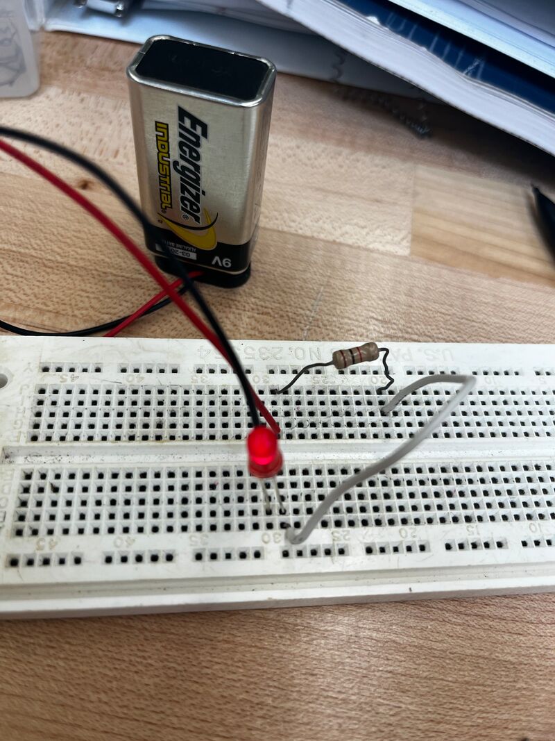
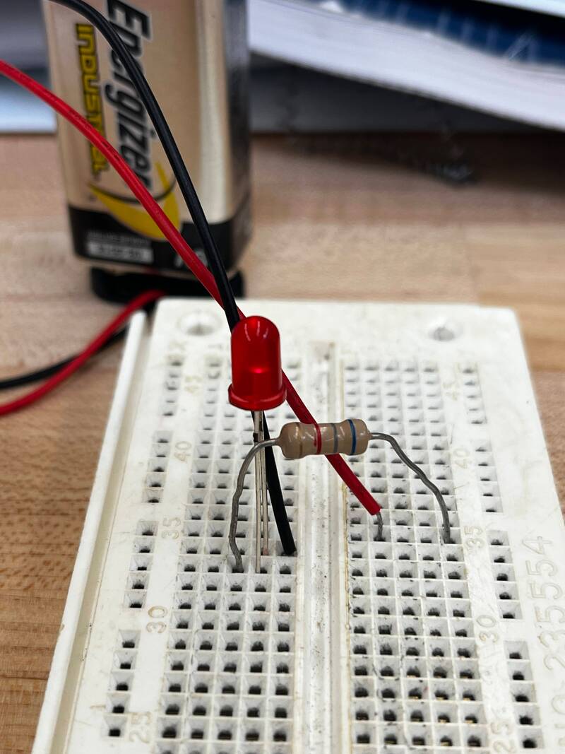
Lab 1 had us make a complete circuit where if you plugged in a battery an LED would turn on. How
The electricity flows from the battery to the resistor which restricts the flow of electricity, on the top picture I have a 100 Ohm resistor so the light is shining brightly, on the bottom picture I have a 6,800 Ohm resistor so the light is much more dim. The electricity then flows from the negative side of the LED through the negative wire from the battery. Why
This introduced us to actually using our breadboard to make things and how to interpret and understand resistors. We learned how LEDs work and that different types of LEDs require different amounts of voltage. |
|
|
Lab 2 LED Brightness Control
|
What
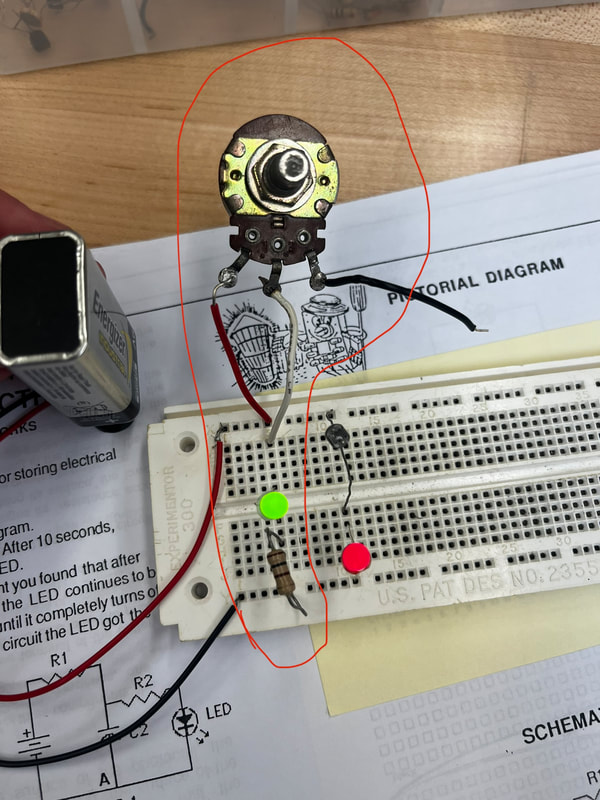
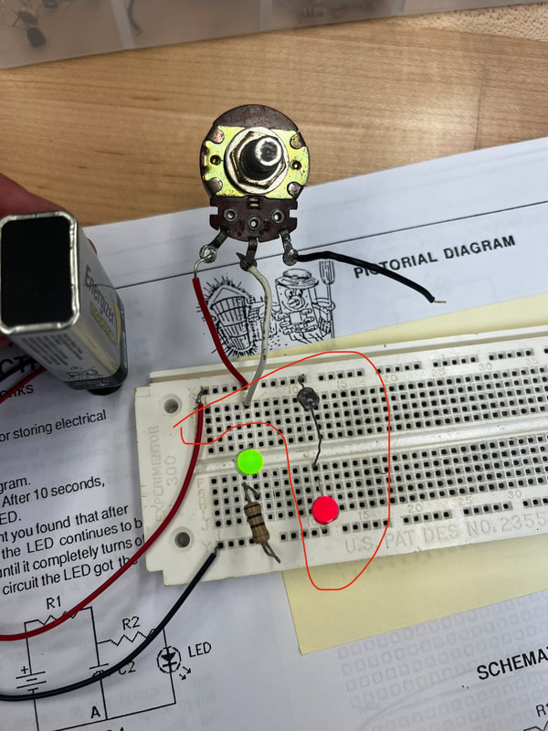
It is a circuit where you can control the amount of current flowing to the LED How Inside of the potentiometer, which is the circular thing is a wiper and a metal strip, depending on where the wiper is on the metal strip will change the resistance. Why If we can easily change the amount of current flowing through a circuit or in this instance an LED we can easily control the amount of light coming from say an LED. Other Feedback This circuit was really easy to do but, I was confused at first because I put in the black wire instead of the white wire. |
Lab 3 Light Activated LED
|
What
It is a circuit where the amount of light the photocell senses controls the current flowing to the LED. How The photocell is very simply, a sensor that senses light, if it sense light it will be on, if it does not sense light it will turn off. Why It is used in street lamps and daylight sensors for things like lights outside. If we can control the time when the lights turn on we can conserve energy easier and it is fully automated. Other Feedback This circuit was also really easy but at first I was confused because my LED wasn't working so I thought my photocell was messed up so I tested that but it was fine, then I thought it might be my LED so i tested it and it didn't work and replaced it. |
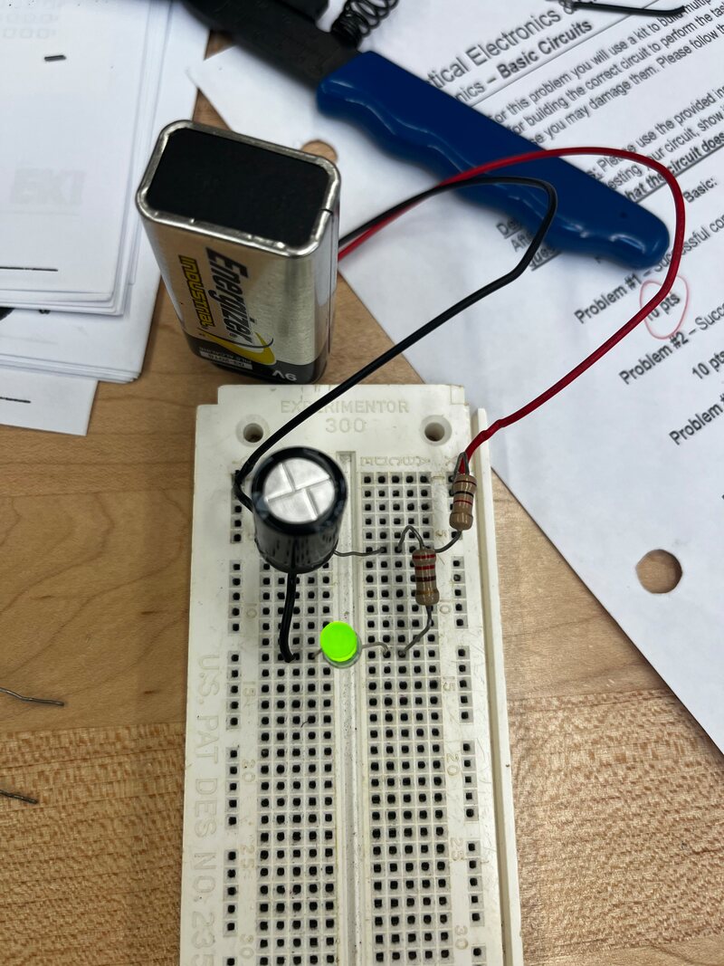
Lab 4 Storage of Electrons
|
What
Lab 4 was a circuit that could stay on for a little bit after being disconnected from it's power source. How When connected to the power source the capacitor, which is the cylindrical object gets charged. There are many different types of capacitors and they each can store a different amount of electrons. When disconnected from the power source the electrons that were stored in the capacitor rapidly leave it and go to the lead, which in this case is an LED. Why Capacitors rapidly discharge electrons that they stored so they aren't good for long term things like batteries are however, they are good if you need a short burst of a large amount of electrons. Other Feedback This circuit confused me at first because when I put the different types of capacitors in I didn't notice a difference until I started to pay attention to the LED more, when I had the 1000 micro farad capacitor in the LED stayed on for about 1.5 seconds, but when I put the 100 micro farad capacitor in it turned off much quicker. |
Lab 5 Speaker Action
|
|
What
Lab 5 is a circuit where when you touch the unconnected end of the speaker to the resistor it will make a noise. How When the speaker receives electrical current the actual speaker part on it creates a vibration which vibrates the air around it. It then sends all the particles around it to bounce off of each other which makes it to our ears. Why We use speakers a lot in our lives. Whether it be for music, our phones or anything else they are in almost every aspect of our lives. If we use a speaker we can use it for a lot of things like, alarms and other things. Other Feedback I had some trouble explaining the how for this because when I first went in to explain it I didn't really understand how sound work so I had to go back and figure out how it works to explain it properly |
Lab 6 Diode Tester
|
|
What
Lab 6 is a circuit that can control the flow of electrons. How Inside of the diode which is the cylindrical object on the bottom has two types of material inside of it. P-type and N-type, P-type has an excess of electrons which allows electrons to not go through it, N-type has a deficiency of electrons which allows them to go through it. When put in the circuit the right way the field will allow electrons to pass through, but when put in the incorrect way the field will widen and not allow electrons to pass through. Why If we need to block electrons from flowing one way and allow them to flow the other way this is very useful because it can do that very easily. Other Feedback This circuit was really easy because you didn't need to think hard about how to put it together, it was very straight forward. |
Lab 7 SCR Checker
|
|
What
Lab 7 is a circuit that can acts as both a diode and a switch. How In the SCR which is the block object with the little piece of metal there is a gate. This gate can be closed by allowing electrons to flow through it which allows electrons to flow from the anode to the cathode. When the gate is opened electrons cannot flow from the anode to the cathode. The only way to open the gate after closing it is to disconnect it from the power source which can be done with a button or by just unplugging the battery. Why If you want to have a diode and a switch in one this is what you need to use, it can be turned on and off and only allows electrons to flow one way. Other Feedback This circuit confused me at first because the SCR was really heating up and wasn't working but, I realised that I completely forget the 1k ohm resistor and when I put that in it started to work and the SCR didn't get hot. |
Lab 8 NPN Translator
|
|
What
Lab 8 is a circuit where the transistor can act as switch and an amplifier. How When electrons flow into the base which is the flat side of the symbol it allows electrons to flow from the collector to the emitter. It acts as an amplifier by using a small current to control a larger current. Why If you need something that can act like a switch and something that amplifies the signal this is what you need. This introduced us to NPN transistors, what they are, and how to use them. |
Lab 9 PNP Transistor Checker
|
|
What
Lab 9 is a circuit that can act as a switch and an amplifier but unlike lab 8 it operates with its polarity reversed. How When electrons flow into the base which is the flat side of the symbol it allows electrons to flow from the collector to the emitter. It acts as an amplifier by using a small current to control a larger current. Why If you need something that can act like a switch and something that amplifies the signal this is what you need. This introduced us to PNP transistors, and how they work. |
Lab 10 Transistor Oscillator
|
|
What
Lab 10 is a circuit that uses two transistors to make a speaker emit a constant noise. How The electrons power the base on the transistors which makes the transistors fight each other, the signal goes back and forth which turns the speaker on and off very quickly which is what makes it emit that noise. Why This lab started to get into deeper concepts and more complicated circuits and how to make them and how they work. |
Lab 11 Blinking Light
|
|
What
How Why |
Lab 13 Safety, Use of Power Sources & Meters
What
We identified safety hazards that can happen while using a power supply and while using multimeters. We familiarized ourselves with multimeters and our power supply. We learned how to operate them and proper operation procedure.
How
We used our multimeters to measure our bodies resistance and measure the voltage drop in a circuit. We also used our meters to measure the amperage within a circuit.
Why
It is important for us to familiarize ourselves with two very important pieces of equipment in our setup. Our power supply allows to easily change the amount of current within a circuit and our multimeters allow us to measure different things within a circuit like voltage, amps, ohms, etc...
Lab 14 Source of Electricity
What
We measured the voltage from thermocouples, solar cells and dry cells. We measured them in series, parallel and different amounts of heat and light.
How
We lit candles under our thermocouples and measured the voltage difference when they were connected in parallel compared to series. We did the same thing with our solar cells and dry cells (batteries) and the result was the same really. In series there is more pressure behind the electricity but in parallel there is more capacity.
Why
Power sources are vital for what we are doing in our class and knowing the difference between them being in parallel compared to series is critical.
Lab 15 Switches and Switching Circuits
What
We identified switches and demonstrated how they operated. We used different types of switches in circuits to watch how the cirucit operated when you put the different types of switches like how DPDT and SPDT worked.
How
We put different types of switches in different circuits and put them in ways where if the switch was flipped one way it was in parallel and when it was flipped the other way it was in series.
Why
Switches are also a vital component in circuits and are used in many circuits. They are used to turn stuff on and off and temporarily stop the flow of electrons.
Lab 16 Ohm's Law
What
How
Why
How
Why
Lab 17 Power, Heat, Light
What
How
Why
How
Why
Burglar Alarm Kit Project
What
How
Why
How
Why
Course Conclusion
This class was pretty easy towards the beginning but it got harder toward the end because it was more independent. The labs from 1-12 were pretty easy and they were fun to do, however when we started doing the burglar alarm I started having trouble. I got everything soldered and my light and buttons work but for some reason my speaker does not work.
